


L298N Dual Motor Driver IC With Heat Sink
Product Code: CIC021Category: IC's
L298N Dual Motor Driver IC With Heat Sink
L298N Dual Motor Driver IC With Heat Sink
L298 is a high power version of L293 motor driver IC. It is a high voltage, high current, dual full-bridge driver designed to accept standard TTL logic levels (Control Logic) and drive inductive loads such as relays, solenoids, DC and Stepper motors. Two enable inputs are provided to Enable or disable the device independently of the input signals. The emitters of the lower transistors of each bridge are connected together and the corresponding external terminal can be used for the connection of an external sensing resistor.
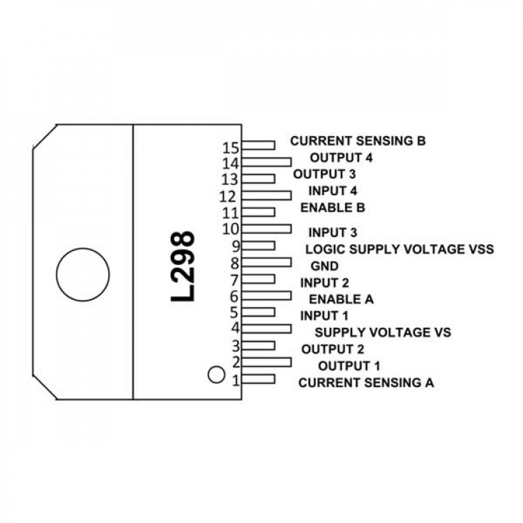
L298 Pin Configuration
L298 is a 15-pin IC as shown in L298 pin diagram and function of each pin is described below.
Pin Name | Description |
COMMON TERMINALS | |
8, GND | Connected to GROUND. |
4, SUPPLY VOLTAGE VS | Connected to +5V. |
9, LOGIC SUPPLY VOLTAGE | Supply Voltage for the Logic Blocks. |
H-BRIDGE A | |
(1) CURRENT SENSING A | Between this pin and ground is connected the sense resistor to control the current of the load. |
(2) OUTPUT 1, (3) OUTPUT 2 | Outputs of the H- Bridge A. The current that flows through the load connected between these two pins is monitored at pin 1. |
(5) INPUT 1, (7) INPUT 2 | TTL Compatible Control Inputs of the Bridge A. |
(6) ENABLE A | TTL Compatible Enable Input. The LOW state for disable. |
H-BRIDGE B | |
(15) CURRENT SENSING B | Between this pin and ground is connected the sense resistor to control the current of the load. |
(13) OUTPUT 3, (14) OUTPUT 4 | Outputs of the H- Bridge B. The current that flows through the load connected between these two pins is monitored at pin 15. |
(10) INPUT 3,(12) INPUT 4 | TTL Compatible Control Inputs of the Bridge B. |
(11) ENABLE B | TTL Compatible Enable Input. The LOW state for disable. |
Features and Specifications
- Operating voltage range: +5 to +46V
- Maximum supply voltage:50V
- Maximum Input and Enable Voltage:+7V
- Maximum current allowed to draw through each output: 3A
- TTL control inputs
- Total power dissipation:25W
- Operating temperature: -23°C to 130°C
- Storage Temperature: -40°C to 150°C
L298N Dual Motor Driver IC With Heat Sink
L298 is a high power version of L293 motor driver IC. It is a high voltage, high current, dual full-bridge driver designed to accept standard TTL logic levels (Control Logic) and drive inductive loads such as relays, solenoids, DC and Stepper motors. Two enable inputs are provided to Enable or disable the device independently of the input signals. The emitters of the lower transistors of each bridge are connected together and the corresponding external terminal can be used for the connection of an external sensing resistor.
L298 Pin Configuration
L298 is a 15-pin IC as shown in L298 pin diagram and function of each pin is described below.
Pin Name | Description |
COMMON TERMINALS | |
8, GND | Connected to GROUND. |
4, SUPPLY VOLTAGE VS | Connected to +5V. |
9, LOGIC SUPPLY VOLTAGE | Supply Voltage for the Logic Blocks. |
H-BRIDGE A | |
(1) CURRENT SENSING A | Between this pin and ground is connected the sense resistor to control the current of the load. |
(2) OUTPUT 1, (3) OUTPUT 2 | Outputs of the H- Bridge A. The current that flows through the load connected between these two pins is monitored at pin 1. |
(5) INPUT 1, (7) INPUT 2 | TTL Compatible Control Inputs of the Bridge A. |
(6) ENABLE A | TTL Compatible Enable Input. The LOW state for disable. |
H-BRIDGE B | |
(15) CURRENT SENSING B | Between this pin and ground is connected the sense resistor to control the current of the load. |
(13) OUTPUT 3, (14) OUTPUT 4 | Outputs of the H- Bridge B. The current that flows through the load connected between these two pins is monitored at pin 15. |
(10) INPUT 3,(12) INPUT 4 | TTL Compatible Control Inputs of the Bridge B. |
(11) ENABLE B | TTL Compatible Enable Input. The LOW state for disable. |
Features and Specifications
- Operating voltage range: +5 to +46V
- Maximum supply voltage:50V
- Maximum Input and Enable Voltage:+7V
- Maximum current allowed to draw through each output: 3A
- TTL control inputs
- Total power dissipation:25W
- Operating temperature: -23°C to 130°C
- Storage Temperature: -40°C to 150°C
Watch this video it will give you a clear idea about this product.
Related Product